
API 650 Tank 3D Design
General arrangement with roof structure, shell courses, stairway, top platform and access interfaces.
REF. 04 · 74 · DETAILED DESIGN
Rev. 14 · October 2026
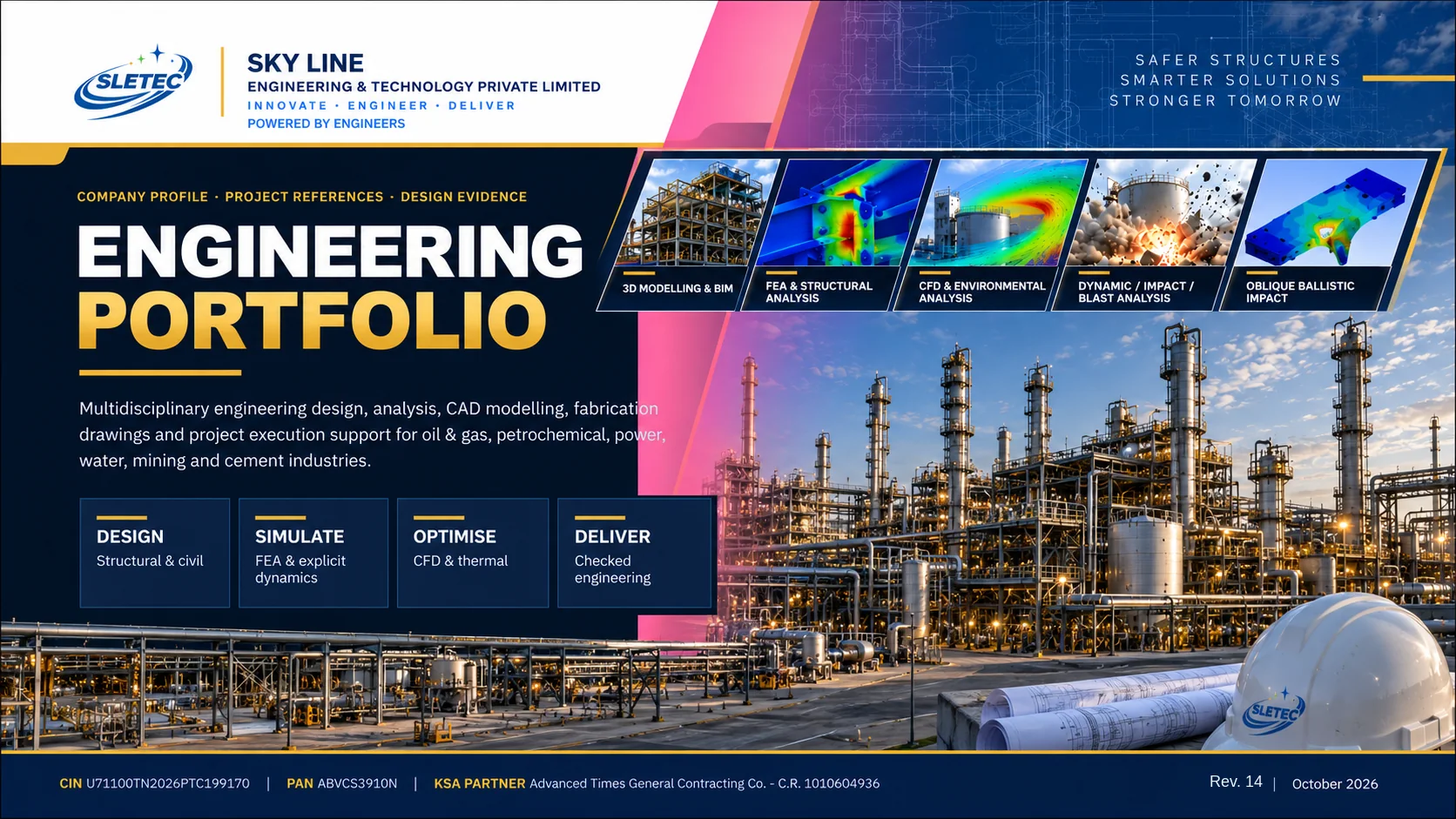
Code-compliant, independently checked, fabrication-ready engineering for oil & gas and industrial projects — design, simulation and documentation delivered from our engineering center in India with in-Kingdom delivery in Saudi Arabia.
Sky Line Engineering & Technology Private Limited · CIN U71100TN2026PTC199170 · KSA Delivery Partner: Advanced Times General Contracting Co.
Chapter 01
Why clients choose SLETEC, a message from the Director and a guide to this portfolio.
02Overview
Why clients choose SLETEC for critical engineering work
A registered engineering company delivering code-compliant, fabrication-ready engineering for industrial clients in Saudi Arabia, India and beyond.
SLETEC combines a dedicated engineering center in Tiruchirappalli with in-Kingdom delivery through its Riyadh partner. Clients receive one coordinated team for design, analysis, documentation and verification — with every deliverable checked, controlled and traceable.
Selected project evidence across tanks, pressure equipment, structural engineering, impact simulation and CFD.
API, ASME, TEMA, AISC, AWS, EN and Saudi Building Code applied to the approved design basis.
Documented design control, document numbering and three-level checking before every issue.
MCA-registered private limited company (CIN U71100TN2026PTC199170) with a C.R.-registered KSA delivery partner.
03Overview
DOCUMENT GUIDE
This document presents selected technical evidence, not a complete list of delivered projects. Additional work, including major industrial assignments, is not published for confidentiality reasons.
Chapter 02
Fence and aerial-barrier engineering, with the technical alignment matrix.
04Barrier engineering
Translating high-consequence loading scenarios into traceable design decisions
DYNAMIC RESPONSE
Nonlinear transient loading • impact orientation • contact and large deformation
BLAST RESPONSE
Pressure/impulse histories • structural response • critical-clearance assessment
STRUCTURAL RESILIENCE
Global load redistribution • member / connection demands • support and foundation interfaces
REVIEW BASIS FROM CUSTOMER REQUIREMENTS
Requirements are a project design basis, not evidence of completed UAV interception or validated final barrier performance.
05Barrier engineering
Relevant methods and evidence - subject to project-specific engineering and verification
| REQUIREMENT | RELEVANT EVIDENCE | CAPABILITY SHOWN | PROJECT HOLD POINT |
|---|---|---|---|
| Normal / oblique UAV impact | Related tower-impact and drop-analysis examples | Explicit transient modelling; response and force transfer | Dedicated UAV / net / cable assessment |
| Nonlinear transient response | LS-DYNA skid-drop and tower-strike studies | Impact acceleration, deformation and load paths | Net / cable / post dynamics and connections |
| Blast response & standoff | Published blast benchmark comparison | Pressure / impulse and deflection correlation | Site-specific loading and clearance checks |
| CFD and surroundings | UAV rotor CFD + building wind / thermal CFD | External flow and loading insight | Site wind / terrain conditions as required |
| Validation / assurance | Mesh checks, energy balance, independent QA | Transparent assumptions and result checks | Client-agreed acceptance and formal review |
Note: Prior simulations establish experience; final UAV and blast acceptance requires approved inputs and verification.
Chapter 03
Tower dynamics, skid drop, nonlinear blast response and benchmark comparison.
06Dynamics & impact
DYNAMIC SIMULATION | SELECTED EVIDENCE
Wind, response-spectrum seismic assessment and accidental crane-impact response.
ENGINEERING BASIS
Modal frequencies and mode shapes; wind and seismic actions; impact response; bolt, weld and anchor forces; global drift and stability checks.
Tower configuration from supplied simulation example.
07Dynamics & impact
EXPLICIT DYNAMICS | SELECTED EVIDENCE
Short-duration contact, impact acceleration, shock transmission and local permanent deformation.
ANALYSIS CAPABILITIES
Corner, edge and flat drop cases; impact velocity; frictional contact; mounting-point acceleration histories; deformation, stress and equipment g-limit checks.
08Dynamics & impact
BLAST SIMULATION | METHODOLOGY
Illustrative method: blast pressure development, reflected impulse and coupled structural deformation.
METHODS DESCRIBED IN SOURCE
CONWEP-based incident blast input, LOAD_BLAST_ENHANCED and MM-ALE. Structural coupling, reflection at boundaries and material nonlinearity require validation against a controlled design basis.
09Dynamics & impact
BLAST VALIDATION | PUBLISHED REFERENCE
Literature-referenced verification example, not a claim of an independently conducted SLETEC field test.
REFERENCE
Han & Liu (2015), Shock and Vibration, and Boyd DSTO-TN-0270 (2000). Published comparison reports a 33 mm test deflection against 32.4 mm (Simulation I) and 36 mm (Simulation II). Peak pressure differences are documented in the cited reference.
Chapter 04
Seventeen flow, thermal and mechanical simulation studies — objective, method and outcome.
10CFD & CAE studies
ADVANCED ENGINEERING | TECHNICAL CASE STUDY
Representative engineering work: modelling, analysis methodology and documented findings.
OBJECTIVE
Enhance propeller aerodynamic efficiency to improve UAV flight endurance. Predict thrust accurately under real-world operating conditions using CFD
TECHNICAL METHOD
Used CFD to simulate thrust, torque, and pressure distribution. Optimized blade geometry to maximize lift and reduce drag losses
ENGINEERING OUTCOME
Increased thrust output with reduced aerodynamic losses.
UAV/rotor aerodynamic case: illustrates CFD expertise; not UAV impact or blast certification.
11CFD & CAE studies
ADVANCED ENGINEERING | TECHNICAL CASE STUDY
Representative engineering work: modelling, analysis methodology and documented findings.
OBJECTIVE
Analyze rotor wake interaction and downwash effects. Understand aerodynamic interference impacting stability and lift
TECHNICAL METHOD
Simulated full quadcopter rotor flow using transient CFD models. Visualized velocity fields and vorticity patterns to assess interference zones
ENGINEERING OUTCOME
Improved quadcopter flight stability in hovering and maneuvering. Optimized rotor spacing for balanced lift and efficiency
UAV/rotor aerodynamic case: illustrates CFD expertise; not UAV impact or blast certification.
12CFD & CAE studies
ADVANCED ENGINEERING | TECHNICAL CASE STUDY
Representative engineering work: modelling, analysis methodology and documented findings.
OBJECTIVE
Evaluate wind flow and temperature distribution around buildings and terrain. Assess solar heat gain and outdoor thermal conditions.
TECHNICAL METHOD
CFD analysis of external airflow, temperature contours and surface heat flux. Evaluated wind velocity, pressure distribution and thermal interaction with building facades and roofs.
ENGINEERING OUTCOME
Identified outdoor hot spots and heat accumulation zones. Supported building orientation and façade design optimization. Improved outdoor thermal environment and energy-efficient design.
UAV/rotor aerodynamic case: illustrates CFD expertise; not UAV impact or blast certification.
13CFD & CAE studies
ADVANCED ENGINEERING | TECHNICAL CASE STUDY
Representative engineering work: modelling, analysis methodology and documented findings.
OBJECTIVE
Evaluate airflow and temperature distribution within data center server rooms. Assess cooling performance, server inlet temperatures and hot-air recirculation.
TECHNICAL METHOD
CFD analysis of server racks, perforated floor tiles, cooling units and hot/cold aisle configurations. Evaluated airflow velocity, temperature contours, pressure distribution and rack inlet temperatures.
ENGINEERING OUTCOME
Improved server inlet temperature uniformity and thermal management. Reduced hot spots and hot-air recirculation. Identified opportunities to improve cooling efficiency and reduce energy consumption.
14CFD & CAE studies
ADVANCED ENGINEERING | TECHNICAL CASE STUDY
Representative engineering work: modelling, analysis methodology and documented findings.
OBJECTIVE
Evaluate evaporative cooling performance of a water misting and fan system in farmhouse outdoor and semi-open spaces.
TECHNICAL METHOD
Developed CFD simulations using the Discrete Phase Model (DPM) to track water droplets, evaporation and spray dispersion.
ENGINEERING OUTCOME
Quantified evaporative cooling potential and temperature reduction around farmhouse living areas. Optimized nozzle placement and droplet size for improved evaporation and cooling coverage.
15CFD & CAE studies
ADVANCED ENGINEERING | TECHNICAL CASE STUDY
Representative engineering work: modelling, analysis methodology and documented findings.
OBJECTIVE
Determine system curve for 800 kW slip ring motor. Estimate cooling air flow rate for effective heat dissipation
TECHNICAL METHOD
Analyze airflow and pressure head across multiple flow rates. Mixed flow fan design was modified with suitable flow guides to meet the cooling flow requirements
ENGINEERING OUTCOME
Reduced recirculation zones, enhancing fan efficiency. Identified required airflow and pressure for safe operation. Enabled accurate system curve for future fan design refinement
16CFD & CAE studies
ADVANCED ENGINEERING | TECHNICAL CASE STUDY
Representative engineering work: modelling, analysis methodology and documented findings.
OBJECTIVE
Improve the shell-and-tube heat exchanger thermal effectiveness to enhance thermal performance and reduce pressure drop.
TECHNICAL METHOD
Performed CFD simulation of shell-side and tube-side flow with guided baffle design and tube bundle layout.
ENGINEERING OUTCOME
Achieved improved heat transfer rate and more uniform flow across the tube bundle, reducing hot-spots and fouling. Reduced pressure drop and structural stress, extending life-cycle and lowering maintenance costs.
17CFD & CAE studies
ADVANCED ENGINEERING | TECHNICAL CASE STUDY
Representative engineering work: modelling, analysis methodology and documented findings.
OBJECTIVE
POC test for swirl vanes. Introduce strong swirl at the motor inlet
TECHNICAL METHOD
Analysis revealed the velocity profiles. CFD used to optimize vane angle, length and placement
ENGINEERING OUTCOME
Desired swirl ratio with minimal design iterations. Increased component life and reduced maintenance
18CFD & CAE studies
ADVANCED ENGINEERING | TECHNICAL CASE STUDY
Representative engineering work: modelling, analysis methodology and documented findings.
OBJECTIVE
Evaluate dry rate at standard distances. Study impact of attachments on airflow and temperature
TECHNICAL METHOD
Performed CFD simulations including heating elements and airflow. Analyzed multiple nozzle designs
ENGINEERING OUTCOME
Minimized need for physical testing. Enabled faster design optimization. Saved time and development cost
19CFD & CAE studies
ADVANCED ENGINEERING | TECHNICAL CASE STUDY
Representative engineering work: modelling, analysis methodology and documented findings.
OBJECTIVE
Analyse polymer flow characteristics and pressure. Optimize screw geometry for uniform melt distribution and minimized power loss.
TECHNICAL METHOD
Implemented dynamic mesh motion to capture screw rotation. Conducted conjugate heat transfer (CHT) to evaluate wall temperature uniformity and cooling performance.
ENGINEERING OUTCOME
Improved mixing efficiency and melt homogeneity. Reduced pressure pulsations and thermal degradation. Enhanced overall volumetric efficiency by ~2-4%.
20CFD & CAE studies
ADVANCED ENGINEERING | TECHNICAL CASE STUDY
Representative engineering work: modelling, analysis methodology and documented findings.
OBJECTIVE
Evaluate the performance and pressure-boost characteristics pneumatic air-booster system. Optimize the flow path and booster valve operation to maintain target output pressure under varying load.
TECHNICAL METHOD
Built a steady/transient pneumatic flow model of the booster module including valve dynamics, piping volumes and leakage paths.
ENGINEERING OUTCOME
Achieved more consistent output pressure under variable input flows. Reduced booster valve switching frequency, leading to improved longevity and system stability.
21CFD & CAE studies
ADVANCED ENGINEERING | TECHNICAL CASE STUDY
Representative engineering work: modelling, analysis methodology and documented findings.
OBJECTIVE
Improve the oil-pump housing design to enhance lubrication performance and reduce leakage engine systems.
TECHNICAL METHOD
Geometry iterations (gallery smoothing, rib additions, thickness optimisation) and structural FEA were employed to optimise flow, thermal and mechanical performance
ENGINEERING OUTCOME
Enhanced flow uniformity reduced stagnant zones, while improved thermal and structural performance lowered risk of leakage and deformation—leading to cost and reliability gains.
22CFD & CAE studies
ADVANCED ENGINEERING | TECHNICAL CASE STUDY
Representative engineering work: modelling, analysis methodology and documented findings.
OBJECTIVE
Design a compact Kaplan turbine for micro-hydro power generation. Ensure reliable 1 kW power output with minimal energy losses
TECHNICAL METHOD
Optimized blade angles for better flow guidance and efficiency. Simulated flow using CFD to evaluate pressure and velocity fields
ENGINEERING OUTCOME
Achieved 1 kW output with 96.5% hydraulic efficiency. Validated overall turbine performance with 82% system efficiency
23CFD & CAE studies
ADVANCED ENGINEERING | TECHNICAL CASE STUDY
Representative engineering work: modelling, analysis methodology and documented findings.
OBJECTIVE
Design a double stage centrifugal pump for 5.4 CMH flow rate. Achieving desired head within compact double-stage configuration
TECHNICAL METHOD
Optimized blade angles and diffuser shape for head and flow. Performed CFD analysis to evaluate pressure rise and flow uniformity
ENGINEERING OUTCOME
Delivered optimized design with reliable 3 kW operational performance. Improved internal flow and reduced hydraulic and mechanical losses
24CFD & CAE studies
ADVANCED ENGINEERING | TECHNICAL CASE STUDY
Representative engineering work: modelling, analysis methodology and documented findings.
OBJECTIVE
Develop a compact 1 kW wind turbine for urban rooftop use
TECHNICAL METHOD
Used CFD analysis to optimize blade aerodynamics and rotor efficiency. Fabrication and validation studies with grid interaction
ENGINEERING OUTCOME
Compact, sustainable solution for urban renewable power generation. Improved power reliability with enhanced aerodynamic performance
25CFD & CAE studies
ADVANCED ENGINEERING | TECHNICAL CASE STUDY
Representative engineering work: modelling, analysis methodology and documented findings.
OBJECTIVE
Design a complete 2D convergent-divergent nozzle yaw vectoring system with actuators.
TECHNICAL METHOD
Conducted 3D CFD simulations for nozzle and transition duct. Evaluated vectoring angles, pressure contours, and thrust output under off-design cases. Developed the actuation mechanism design.
ENGINEERING OUTCOME
The CFD results were validated against test data and was found to be in good agreement.
26CFD & CAE studies
ADVANCED ENGINEERING | TECHNICAL CASE STUDY
Representative engineering work: modelling, analysis methodology and documented findings.
OBJECTIVE
Design a high-efficiency combustion chamber for aero gas turbine application. Ensure low pressure loss and uniform temperature distribution at turbine inlet
TECHNICAL METHOD
Used CFD and CHT simulations to optimize primary and dilution zones & CHT Simulation for Heat transfer studies. Tuned swirler configuration and hole patterns for efficient mixing and flame stability
DESIGN CHALLENGES
Balancing compact design with performance and maintainability requirements. Minimizing pressure loss across combustor while ensuring effective mixing.
Chapter 05
Senior structural engineering profiles behind high-consequence design and verification.
27Expertise
Senior structural engineering profiles relevant to high-consequence industrial design and verification
STRUCTURAL ANALYSIS SPECIALIST / BDM
B.E. Civil Engineering
ENGINEERING TOOLS
STAAD.Pro • SACS • ETABS • SAFE • Tekla
LEAD CIVIL / STRUCTURAL ENGINEER
M.Tech. Structural • B.E. Civil • M.B.L.
ENGINEERING TOOLS
STAAD.Pro • ETABS • SAFE • SACS • MIDAS
CIVIL & STRUCTURAL ENGINEERING
Experience in civil and structural engineering
Structural design, analysis and engineering support.
01
SECTION 01
A registered engineering company with an India engineering center and in-Kingdom delivery in Saudi Arabia.
29Company
Statutory registration details of SLETEC and its Saudi delivery partner
INDIA — REGISTERED COMPANY
KINGDOM OF SAUDI ARABIA — DELIVERY PARTNER
Design, analysis and documentation delivered by SLETEC
KSA contracts and registrations through ATC
Each company responsible for its own obligations
Registration details verifiable at mca.gov.in
30Company
Engineering support for industrial assets, equipment packages and fabrication-ready deliverables
WHO WE ARE
CUSTOMER VALUE
OUR COMMITMENT
02
SECTION 02
Eight engineering disciplines, eight analysis methods and the international codes that govern them.
32Capabilities
Eight core disciplines delivered by one coordinated engineering team
| DISCIPLINE | SCOPE OF SERVICES | TYPICAL DELIVERABLES |
|---|---|---|
| Storage tanks & silos | New tank design, roofs, shells, bottoms, nozzles, anchors, access; repair, alteration, bulging and failure investigation; silo structural and flow studies | Calculations, GA & fabrication drawings, repair procedures, FEA reports |
| Pressure vessels & static equipment | Vessels, separators, filters, reactors, adsorbers; nozzle and local stress; lifting devices; fatigue and creep evaluation | Design calculations, data sheets, FEA & fatigue reports |
| Heat exchangers | Shell-and-tube thermal and mechanical design, rerating, nozzle-load assessment, bellows replacement | Thermal/mechanical calcs, TEMA sheets, drawings |
| Piping & process systems | Layouts, isometrics, supports, tie-ins, flexibility and stress analysis, waterhammer, GRP piping | Stress reports, support details, isometrics |
| Structural & civil | Platforms, racks, stairs, supports, anchors, foundations, skids; wind and seismic checks; vibration assessment | Structural calcs, steel & foundation drawings, MTO |
| Engineering analysis | Linear/non-linear FEA, buckling, modal/harmonic, fatigue, explicit impact, CFD flow and particle studies | Analysis reports with basis and acceptance criteria |
| Reverse engineering & fabrication | Field-to-CAD reconstruction, 3D modelling, shop drawings, BOM and cutting lists | 3D models, manufacturing drawings, BOM/MTO |
| Inspection, FFS & QA/QC documents | Fitness-for-service, inspection and tolerance validation, ITP/QCP, NDT plans, MDR dossiers | FFS reports, ITP/QCP, MDR/NMR, as-built records |
33Capabilities
Analysis types used to verify designs, assess damage and support engineering decisions
Stress, deformation, plastic collapse, local stress at nozzles and supports
ASME VIII Div. 2 Part 5, WRC 107/537
Shell, roof and structural stability under external pressure, wind and vacuum
API 650, ASME VIII, EN 1993
Natural frequency, mode shape and forced response of skids, platforms and equipment
Project criteria, OEM limits
Cyclic pressure, thermal and nozzle loads; weld fatigue; high-temperature creep
ASME VIII Div. 2, EN 13445
High-velocity impact, penetration and erosion; drop and crash events
Ansys Explicit Dynamics
Temperature fields and thermal stress in coolers, drives and furnace components
Project specification
Pressure drop, velocity fields, venting, transient flow and silo discharge
Project specification
Damage assessment, bulging, corrosion and remaining-life evaluation
API 579-1 / ASME FFS-1
TOOLS ON REFERENCED PROJECTS
Ansys Workbench (Mechanical, Explicit Dynamics) · Ansys SpaceClaim · 3D CAD and 2D drafting tools to client requirements · hand calculations and code-based spreadsheets for independent verification
34Capabilities
International codes applied across SLETEC engineering assignments
API / TANKS
API 650, API 620, API 653, API 2000, API 579 / ASME FFS-1
Tanks, roofs, shells, bottoms, nozzles, anchors, access systems and repair engineering.
ASME / STATIC EQUIPMENT
ASME VIII Div. 1 & 2, ASME II, V & IX, TEMA, WRC 107/537, EN 13445, PD 5500
Pressure vessels, exchangers, separators, filters, reactors, adsorbers and local-stress checks.
PIPING / PROCESS
ASME B31.3, ASME B31.1, ISO 14692, NACE MR0175 / ISO 15156
Layouts, isometrics, supports, tie-ins, flexibility, waterhammer and GRP systems.
STRUCTURAL / CIVIL
AISC 360, AWS D1.1/D1.6, ACI 318, ASCE 7, SBC, Eurocode / BS, ASTM / EN
Platforms, racks, stairs, supports, anchors, foundations, wind and seismic verification.
QA / NDT / COATING
ASNT SNT-TC-1A, ISO 9712, ISO 12944, ISO 8501-1, SSPC / NACE
ITP/QCP, NDT plans, material traceability, coating systems and release dossiers.
DOCUMENT CONTROL
NMR, MDR, MRB, MTO, BOM, BOQ, redline, as-built and closeout registers
Controlled issue, revision, transmittal and customer-submission support.
35Capabilities
Sectors and asset types covered by SLETEC project references
Refineries, storage terminals, process plants
Tanks, vessels, piping, pig traps, FCC and H2 reactors
Process units and utilities
Exchangers, adsorbers, separators, filters
Steam systems and auxiliaries
Steam piping, coolers, silencers, drive trains
Treatment and fire-water systems
GRP piping, water tanks, fire-water pump skids
Bulk handling plants
Silos, batching plants, conveyors, structures
Fabrication and machinery
Chassis, booths, skids, reverse engineering
36Capabilities
Disciplines across the asset lifecycle — from concept through fabrication and site support
| DISCIPLINE | CONCEPT & BASIC | DETAILED DESIGN | ANALYSIS & VERIFICATION | REPAIR / FFS | FABRICATION DOCUMENTS | SITE & VENDOR SUPPORT | TYPICAL ENGINEERING DELIVERABLES |
|---|---|---|---|---|---|---|---|
| Storage tanks & silos | Tank / roof FEA GA + detail drawings | ||||||
| Pressure vessels & static equipment | Vessel verification Design calculations | ||||||
| Heat exchangers | Thermal rerating Mechanical checks | ||||||
| Piping & process systems | Flexibility review Support / layout details | ||||||
| Structural & civil | Structural FEA Steel / foundation calcs | ||||||
| Engineering analysis (FEA / CFD) | FEA / CFD / dynamics Verified reports | ||||||
| Reverse engineering | 3D CAD and as-built Fabrication drawings | ||||||
| Inspection, FFS & risk studies | FFS / inspection QA/QC dossiers |
Core capability On request / with partners Capability matrix; the project examples presented are a non-exhaustive selection.
03
SECTION 03
A selected view of a substantially wider engineering record. From targeted analyses to major industrial engineering packages; confidential client assignments are intentionally not shown.
38Project evidence
New tank design, structural verification and silo engineering
General arrangement with roof structure, shell courses, stairway, top platform and access interfaces.
REF. 04 · 74 · DETAILED DESIGN
Total deformation, stress, buckling and serviceability evidence for roof stiffness and maximum displacement.
REF. 16 · 40 · FEA
Design data, nozzle schedule, material specification and fabrication basis for a cement silo.
REF. 05 · FABRICATION BASIS
SCOPE
Tank sizing, shell/roof/bottom design, nozzles, anchors, access systems
CODES
API 650 · API 620 · API 2000 · ASCE 7
DELIVERABLES
Calculations, GA & fabrication drawings, FEA reports
39Project evidence
Access arrangements, load paths and high specific-gravity loading
Scaffold, fall-protection and tank-roof interface for access through a roof manhole.
REF. 77 · SAFETY VERIFICATION
Gravity, wind and concentrated reactions around roof openings, with support reaction check.
REF. 77 · 78 · STRUCTURAL
1.83 SG fluid, pressure gradient, shell stress and deformation checks at 4,450 mm fill height.
REF. 79 · HYDROSTATIC FEA
SCOPE
Roof access, temporary works, anchors, hydrostatic shell checks
CODES
API 650 · AISC 360 · project criteria
DELIVERABLES
Verification reports with reactions and acceptance checks
40Project evidence
Repair planning, temporary supports and structural response
Localised shell replacement, manway work and internal support arrangement.
REF. 01 · REPAIR ENGINEERING
1.83 SG liquid loading, shell stress, deformation and repair verification.
REF. 79 · SHELL VERIFICATION
Temporary stiffening, shell stability, wind response and buckling review.
REF. 02 · 43 · REPAIR FEA
SCOPE
Repair methodology, temporary works, bottom/roof replacement, FFS
CODES
API 653 · API 650 · API 579-1 / ASME FFS-1
DELIVERABLES
Repair procedures, calculations, inspection & tolerance records
41Project evidence
Pressure equipment design, local stress and lifting verification
Integrated vessels, piping interfaces, platforms and support layout for plant coordination.
REF. 31 · PACKAGE ENGINEERING
Nozzle, connection and local-stress verification of an exchanger shell and supports.
REF. 32 · WRC 537 / FEA
Lifting lugs, shell, dish and local component checks with mesh, stress and deformation plots.
REF. 17 · 19 · LIFTING FEA
SCOPE
Vessels, separators, filters, reactors, exchangers, lifting devices
CODES
ASME VIII Div. 1 & 2 · TEMA · EN 13445 · PD 5500
DELIVERABLES
Design calcs, data sheets, FEA and fatigue reports
42Project evidence
Comment closure, anchor verification and cyclic-service assessment
Controlled methodology, technical comments, material and QA/QC response closure.
REF. 20 · DOCUMENT CONTROL
Anchor stress, deformation, safety factor and modal response verification.
REF. 78 · STRUCTURAL FEA
Cyclic pressure, nozzle loads, weld stress and fatigue-life assessment.
REF. 80 · FATIGUE ANALYSIS
SCOPE
Repair package control, anchor design checks, fatigue screening
CODES
ASME VIII Div. 2 Part 5 · API 653 · EN 795 (anchors, where specified)
DELIVERABLES
Comment-response sheets, verification and fatigue reports
43Project evidence
Routing coordination and flow performance verification
Buildable routing, nozzles, valves, access ladder and platform interfaces for clash review.
REF. 37 · 64 · LAYOUT
Transient pressure field for a vent return pipe and silo response, time-stepped.
REF. 05 · 53 · CFD
Transient velocity distribution and process-flow review during silo loading.
REF. 05 · CFD
SCOPE
Layouts, supports, flexibility, waterhammer, CFD pressure drop
CODES
ASME B31.3 · ASME B31.1 · ISO 14692
DELIVERABLES
Stress reports, support details, isometrics, CFD reports
44Project evidence
Steelwork, foundations and structural verification
CF8 footing plan, PD2 / PD5 pedestals, reinforcement and sectional details.
FOUNDATION ENGINEERING - DETAIL DRAWING
Platforms, stairs, framing and material schedules for fabrication and installation.
REF. 39 · STEELWORK
Total deformation and load-path verification of a steel platform structure.
REF. 52 · STRUCTURAL FEA
SCOPE
Platforms, racks, supports, anchors, foundations, skids
CODES
AISC 360 · AWS D1.1 · ACI 318 · ASCE 7 · SBC
DELIVERABLES
Structural calcs, steel & foundation drawings, MTO
45Project evidence
Reinforced concrete footing plan, pedestal reinforcement and section details
46Project evidence
Shop-ready drawings and field-to-CAD reconstruction
Painting booth mono-rail general arrangement, details, parts and bill of materials.
FABRICATION DRAWINGS
Structural platform assembly drawings, BOM, cutting information and controlled revisions.
MANUFACTURING PACKAGE
Station reverse engineering — general arrangement, piping interfaces and detailing.
REF. 03 · REVERSE ENGINEERING
SCOPE
3D modelling, shop drawings, BOM/MTO, reverse engineering
CODES
ISO / ASME drafting standards · AWS D1.1 weld symbols
DELIVERABLES
3D models, GA & detail drawings, BOM, cutting lists
47Project evidence
Dynamic, flow and structural response evaluation
Frequency response, mode shape and serviceability verification of a supported frame.
MODAL ANALYSIS
Material recirculation, discharge behaviour and unloading validation.
REF. 05 · PARTICLE CFD
Load-path and deformation verification of a platform deck under operating loads.
STRUCTURAL FEA
SCOPE
Modal, harmonic, fatigue, CFD and particle-flow studies
METHOD
Documented mesh, boundary conditions, load cases and acceptance criteria
DELIVERABLES
Analysis reports with design basis and recommendations
48Project evidence
Equipment support assessment and proposed stiffening for a diesel-engine-driven fire water pump skid
Base-frame arrangement with added stiffening members for engineering assessment.
REF. 81 · STIFFENING DESIGN
Equipment-weight load case: displacement and stress contours for the assessed model.
REF. 81 · STATIC FEA
Natural-frequency and mode-shape review. Mode-shape displacement is not operating vibration.
REF. 81 · MODAL FEA
SCOPE
Equipment-weight, modal and harmonic studies; stiffening design
BASIS
Engine and pump excitation per supplied data; project acceptance criteria
OUTCOME
Stiffening proposal with site verification recommendations
49Project evidence
Combined engine and pump excitation and mounting-face response
Calculated deformation under combined engine and pump excitation at the reported frequency.
REF. 81 · HARMONIC FEA
Mounting-face X-direction velocity response across the analysed frequency range.
REF. 81 · FREQUENCY SWEEP
Mounting-face X-direction velocity response across the analysed frequency range.
REF. 81 · FREQUENCY SWEEP
NOTE
Response calculated under assumed excitation; not an operating RMS measurement
ACCEPTANCE
Site vibration acceptance requires field verification
DELIVERABLES
Harmonic analysis report, response plots, recommendations
50Project evidence
Chassis, batching plant and silo engineering
Chassis reconstruction and structural assessment: scan data, CAD model and dimensions.
REF. 03 · REVERSE ENGINEERING
Engineering package for a wet concrete batching plant, including equipment and layout interfaces.
REF. 06 · PLANT ENGINEERING
Multi-silo structural and flow assessment; particle-flow behaviour during loading.
REF. 05 · CFD / STRUCTURAL
SCOPE
Scan-to-CAD, structural assessment, plant layout packages
INTERFACES
Equipment, conveyors, silos, foundations and access
DELIVERABLES
3D models, GA drawings, assessment reports
Chapter 09
Problem, approach and outcome on selected engineering assignments.
51Case studies
How SLETEC engineering turns client problems into verified, buildable solutions
REF. 79 · STORAGE TANK
CHALLENGE
Confirm the safe filling height when an existing Ø6,096 mm, 5.3 mm-shell vertical tank stores a 1.83 SG fluid.
APPROACH
Static-structural FEA of the shell under hydrostatic pressure gradient, with deformation and stress review against the target stress level.
OUTCOME
Filling height of 4,450 mm established at a maximum shell stress of 48.02 MPa — a clear operating limit for the owner.
REF. 77 · ACCESS SAFETY
CHALLENGE
Verify a scaffold arrangement entering through a roof manhole without overloading the dome roof.
APPROACH
FEA of roof and scaffold interface under gravity, wind and scaffold reactions; global equilibrium and reaction checks.
OUTCOME
Max vertical deformation +0.51 mm with total support reaction ≈ 4.90 × 10⁴ N — access approved within serviceability limits.
REF. 81 · VIBRATION
CHALLENGE
Address vibration concerns on a diesel-engine-driven fire water pump skid base frame.
APPROACH
Equipment-weight static, modal and harmonic FEA under combined engine and pump excitation; stiffening options modelled.
OUTCOME
Stiffening design proposed with site-verification recommendations for vibration acceptance.
REF. 01 · 02 · REPAIR
CHALLENGE
Restore an in-service storage tank with damaged shell plates, bottom and roof structure.
APPROACH
Repair methodology with localised shell replacement, temporary internal supports and FEA of temporary stiffening, stability and wind.
OUTCOME
Controlled repair package with procedures and calculations for safe execution and return to service.
REF. 80 · ASME VIII DIV. 2
CHALLENGE
Demonstrate the fatigue life of an adsorber subject to repeated pressure cycling and nozzle loads.
APPROACH
Fatigue assessment to ASME VIII Division 2 using FEA of shell, nozzles and welds under cyclic pressure.
OUTCOME
Fatigue evaluation documented against the agreed criteria, supporting the vessel’s cyclic-service approval.
REF. 05 · CFD
CHALLENGE
Check whether material recirculation during loading could congest the silo top filter.
APPROACH
Transient CFD with particle tracking of the loading process and recirculation review.
OUTCOME
No material recirculation at the silo top — the top filter is safe from particle congestion.
Chapter 10
Multi-industry evidence across equipment, structures and simulation.
53Gallery
Selected technical images only - further projects and client-restricted deliverables are not displayed.
Chapter 11
Eighty-two selected references, grouped by discipline and code basis.
54Project references
SELECTED REFERENCES ONLY | Many larger projects are omitted to protect client confidentiality.
04
SECTION 04
How we engage, what you receive and the quality, HSE and security standards behind every job.
57Delivery & quality
Flexible ways to work with SLETEC — from a single calculation to a dedicated engineering team
Complete design or verification package for a defined scope, price and schedule.
Flexible man-hour support for owners and contractors as needs arise.
A team at our India engineering center working as an extension of your project office.
Independent checking of designs, calculations, vendor documents and FEA models.
HOW A PROJECT STARTS
Contracting in Saudi Arabia: through Advanced Times General Contracting Co. (C.R. 1010604936), with SLETEC as engineering office.
India & international: directly with SLETEC (CIN U71100TN2026PTC199170). NDAs and client-specific terms accepted.
58Delivery & quality
Consistent design records, transparent calculations and controlled engineering issue
DELIVERABLES
Engineering calculations | CAD / analysis models | GA and fabrication drawings | BOM / MTO | revision records | closeout dossier
Every project report is issued to the approved design basis with documented review and checking.
59Delivery & quality
Controlled workflow aligned with documented engineering quality procedures (SLT-QMS-PR-01 to 03)
THREE-LEVEL VERIFICATION
DOCUMENT CONTROL
DELIVERABLES
60Delivery & quality
Policies that govern every assignment, and how to start a project
QUALITY POLICY
SLT-QMS-POL-01
HSE POLICY
SLT-HSE-POL-01
INFORMATION SECURITY
REQUEST A PROPOSAL
SLETEC reviews the package and responds with a coordinated technical and commercial proposal.
Chapter 13
Registered offices, engineering center and KSA delivery partner.
61Contact
Engineering support for industrial assets, equipment packages and fabrication-ready deliverables
PROJECT ENQUIRIES
enquiry@sletec.com
engineering@sletec.com
www.sletec.com
TELEPHONE / WHATSAPP
KSA +966 55 545 8298
India +91 90430 07737
INDIA — REGISTERED OFFICE
Sky Line Engineering & Technology Private Limited
D-46, 8th Cross West, Thillai Nagar, Tiruchirappalli – 620018, Tamil Nadu, India
CIN U71100TN2026PTC199170 · PAN ABVCS3910N
INDIA — ENGINEERING CENTER
1/N No. 32, Keela Street, Mela Sridevi Mangalam, Manachanallur Post, Tiruchirappalli Rural – 621005, Tamil Nadu, India
SAUDI ARABIA — DELIVERY PARTNER
Advanced Times General Contracting Co.
Office 14/A, 2nd Floor, Rasheed & Othaim Center, Salah Al-Din St. (60), Al Malaz, Riyadh 12642
C.R. 1010604936 · VAT 311109717400003
Additional experience can be discussed where disclosure is authorised by the relevant client.
ENGINEERED SOLUTIONS. DELIVERED EXCELLENCE.
Start a project
Send your scope, drawings, codes and schedule — SLETEC reviews the package and responds with a coordinated technical and commercial proposal.